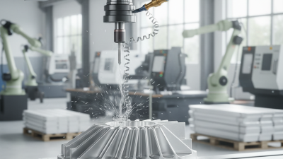
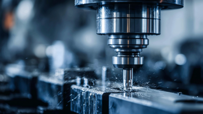
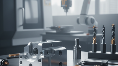
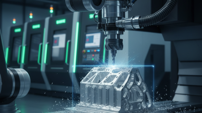
Aluminum machining is the controlled removal of material from aluminum blocks, plates, or castings. It creates accurate parts for aerospace, automotive, electronics, medical equipment, and industrial systems. Unlike softer materials, aluminum can cut quickly, yet it may stick to a tool when heat and friction rise. That contradiction makes the process both efficient and demanding.
In a typical workshop, the job begins with a digital drawing and a carefully selected alloy. Engineers review dimensions, tolerances, wall thickness, and the final part’s working conditions. CNC machines then guide drills, mills, or turning tools along programmed paths. Operators still inspect the surface, edges, and critical measurements. That human check matters. A computer can follow instructions perfectly, but a poor setup can repeat the same mistake across every part.
Tool geometry, cutting speed, feed rate, and coolant choice influence the result. Too much heat may cause burrs, discoloration, or dimensional changes. Too little rigidity can leave vibration marks on a flat face. These details sound technical because they are. However, they become visible in practice: a dull cutter leaves a rough edge, while a stable setup produces clean chips and a bright surface.
No setup is perfect. Experienced machinists still adjust their approach after testing the first part. This article explains how aluminum machining works, from material selection and tool movement to finishing and quality inspection. It also considers common limitations, because reliable manufacturing depends on honest evaluation, not confident assumptions.
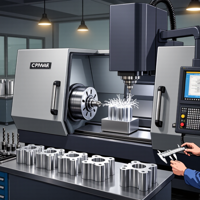
Aluminum machining is the controlled removal of material from an aluminum workpiece. Cutting tools shape the part according to a digital design. Common operations include milling, turning, drilling, and tapping. It is not magic. Each cut depends on speed, feed rate, tool geometry, and material condition.
Aluminum is valued for its low weight, corrosion resistance, and practical strength. These qualities support parts used in transportation, electronics, equipment, and precision assemblies. Machining also creates accurate holes, smooth surfaces, and complex profiles. A technician may watch silver chips curl from a cutter while coolant keeps the edge stable. Small errors matter. Excessive heat can distort thin walls or leave unwanted burrs.
The process matters because reliable dimensions help components fit and function consistently. Engineers often specify tight tolerances when a part must align with another component. Inspectors then check critical features with gauges, coordinate measuring equipment, or calibrated hand tools. In practice, the first machined part may reveal weaknesses in the design. A pocket can be too deep, or a narrow corner can vibrate during cutting. That feedback should lead to adjustment, not denial. Aluminum machining is efficient, but it still requires judgment, maintenance, and careful inspection. A clean surface does not always prove that every dimension is correct.
What Is Aluminum Machining and How Does It Work?
How Aluminum Properties Affect the Machining Process
Aluminum is light, thermally conductive, and relatively soft, so it cuts differently from steel. The Aluminum Association reports that aluminum weighs about one-third as much as steel, with a density near 2.70 g/cm³. This lower mass helps reduce machine loads and supports faster tool movement. However, softness can create problems. A sharp cutting edge may smear material instead of removing it cleanly. Built-up edge can then appear on the tool, leaving a dull streak across the workpiece.
Heat behavior matters too. ASM Handbook data lists thermal conductivity around 167 W/m·K for 6061-T6 aluminum. Much of the cutting heat can travel into the part rather than the tool. That sounds beneficial, but thin walls may expand during machining. Dimensional errors can appear after the part cools. The trade-off is easy to underestimate. A machinist should control chip evacuation, use suitable rake geometry, and avoid rubbing at low feed rates. The International Organization for Standardization also emphasizes process control for dimensional accuracy in metalworking operations. In practice, cutting data from a handbook is only a starting point. Fixture stiffness, alloy condition, tool wear, and coolant delivery can change the result. A clean, curled chip is useful evidence. A shiny surface is not always proof of a stable process.
| Machining Factor | Relevant Aluminum Property or Condition | Typical Data or Range | Effect on the Machining Process | Common Process Response |
|---|---|---|---|---|
| Material Removal | Low density | Approximately 2.70 g/cm³ for commercially pure aluminum and many common alloys | Aluminum workpieces are relatively lightweight, which reduces handling effort and cutting force compared with many steels. | Use secure workholding and avoid excessive clamping force that could distort thin sections. |
| Cutting Speed | Relatively low hardness and high machinability in suitable grades | Common CNC milling speeds may range from about 150 to 600 m/min, depending on alloy, tool, diameter, and setup | Higher cutting speeds are often possible, but the correct value depends strongly on tool geometry, machine rigidity, and chip evacuation. | Set speeds using tool-maker recommendations and adjust for workholding, tool diameter, and alloy condition. |
| Feed Rate | Ductility and tendency to form long, continuous chips | Typical milling feed per tooth may be approximately 0.05–0.30 mm/tooth for many general-purpose applications | Too little feed can cause rubbing and built-up edge; too much feed can increase burrs, deflection, and cutting load. | Choose a positive feed rate that produces a real chip and maintain a stable chip load. |
| Tool Material | Aluminum can adhere to cutting edges during machining | Polished carbide and suitable high-speed steel tools are widely used | Adhesion can change the effective cutting geometry, increase friction, and damage the machined surface. | Use sharp, polished, high-clearance tools designed for non-ferrous metals. |
| Tool Geometry | Soft, ductile material behavior in many alloys | Positive rake angles and two- or three-flute milling cutters are commonly used for chip clearance | Positive geometry lowers cutting resistance and helps prevent chips from packing into flutes. | Select a sharp edge, adequate flute space, and geometry suited to the specific alloy and operation. |
| Thermal Management | High thermal conductivity | Approximately 120–235 W/(m·K), depending on alloy and temper | Heat is transferred quickly through the workpiece, but friction from a dull tool can still cause localized heating and adhesion. | Keep the tool sharp, use an appropriate coolant or mist where permitted, and prevent chip recutting. |
| Dimensional Stability | High coefficient of thermal expansion | Approximately 21–24 µm/(m·K) for many aluminum alloys | Temperature changes can affect workpiece dimensions during tight-tolerance machining. | Control shop temperature, allow parts to stabilize, and inspect at a consistent reference temperature. |
| Surface Finish | Ductility and built-up edge risk | Surface roughness depends on tool condition, feed, tool nose radius, rigidity, and coolant; values around Ra 0.8–3.2 µm are common for general CNC finishing | A sharp tool and stable cutting action can produce a smooth surface, while adhesion may create tearing or smearing. | Use a dedicated finishing pass, sharp tooling, controlled feed, and clean chip evacuation. |
| Burr Formation | Ductile material that plastically deforms at exits and edges | Burr size varies with alloy, edge sharpness, cutting direction, feed, and part geometry | Exit edges and thin walls may develop rolled or breakout burrs. | Use climb milling where appropriate, support thin features, and add deburring or edge-breaking operations. |
| Work Hardening | Some wrought alloys can harden locally when rubbed or repeatedly deformed | The amount depends on alloy, temper, deformation, and cutting conditions | Tool rubbing can create a harder surface layer and accelerate tool wear. | Avoid dwelling, maintain adequate chip thickness, and replace or recondition dull tools. |
| Alloy Selection | Mechanical properties vary significantly by alloy and temper | 6061-T6: approximately 276 MPa yield strength; 7075-T6: approximately 503 MPa yield strength; published values vary by product form and specification | Stronger alloys may increase cutting forces and tool wear, while softer alloys may be more prone to adhesion and burrs. | Select the alloy and temper according to strength, corrosion resistance, formability, and machining requirements. |
| Chip Control and Safety | Long chips and low-density chips can become entangled | Chip behavior changes with alloy, tool geometry, feed, speed, and coolant application | Continuous chips can damage surfaces, obstruct the cutting zone, and create a handling hazard. | Use chip-breaking strategies, reliable chip evacuation, guarding, and appropriate personal protective equipment. |
Note: Values are representative engineering ranges. Actual machining parameters and material properties vary with alloy designation, temper, product form, tool design, machine capability, coolant, and workholding conditions.
The main steps in aluminum machining begin with a clear engineering drawing. The machinist checks tolerances, hole sizes, surface finishes, and material grade. A suitable aluminum billet or plate is then selected. The wrong grade can distort during cutting or fail under load.
Workholding comes next. The stock must stay rigid without excessive clamping pressure. Aluminum is softer than steel, so sharp cutting tools and correct rake angles help prevent built-up edges. Roughing removes most material quickly, while finishing creates accurate walls, holes, and smooth surfaces.
Cutting speed, feed rate, and coolant flow must remain balanced. Excessive heat can warp thin sections. According to the U.S. Geological Survey’s Mineral Commodity Summaries 2024, global primary aluminum production reached about 70 million metric tons in 2023. The International Aluminium Institute also reports that recycled aluminum requires roughly 5% of the energy used for primary production, making scrap control important during machining.
Tips: Keep chips moving away from the cutter. Inspect the first finished part carefully. A small burr can hide a larger alignment problem. Use a deburring tool, then measure critical features with calibrated gauges. In practice, no setup is perfect. Thin parts may vibrate, even after careful planning. I have found that reducing tool engagement often improves the finish more than simply increasing cutting speed. Record the final settings for repeat work, but question them when the material, geometry, or machine changes.
Aluminum machining removes material with controlled cutting tools to create precise parts. CNC milling is common for slots, pockets, contours, and drilled holes. A rotating spindle drives an end mill through the workpiece. CNC turning uses a lathe, where the material rotates against a fixed cutting tool. Saws can prepare rough blanks before detailed machining begins. Aluminum cuts easily, but it can stick to dull tools.
Tool selection affects surface quality, chip control, and production time. Sharp carbide end mills often provide clean cuts and stable edge life. Variable flute spacing can reduce vibration during pocketing. Drills need proper clearance so chips leave deep holes instead of packing inside. Clamps must hold the part firmly without distorting thin walls. Coolant or cutting fluid may reduce heat and prevent built-up material on the tool. However, excessive fluid can hide chip problems. No setup is perfect.
Tips: Use sharp tools and moderate cutting parameters. Adjust spindle speed, feed rate, and cutting depth for the alloy and machine. Keep chips away from the cutting zone. Check the first part with calipers, micrometers, or a coordinate measuring machine. Look for burrs around holes and edges. Deburring improves handling and assembly, but aggressive polishing can change dimensions. Experienced machinists also inspect tool wear during the run, because aluminum may appear smooth while accuracy is gradually declining.
Carbide tools are commonly used for aluminum because they support high cutting speeds and efficient heat removal. The ranges below are typical engineering starting points in meters per minute (m/min); the final setting depends on the alloy, tool geometry, tool diameter, machine rigidity, coolant, and required surface finish.
Milling can use a higher cutting-speed range because multiple cutting edges share the work. Drilling and reaming generally use lower speeds to control heat, chip evacuation, and hole accuracy.
Aluminum machining removes material from a solid billet, plate, or casting using rotating cutters or turning tools. CNC milling creates pockets, slots, and complex contours, while turning produces cylindrical parts. Aluminum cuts efficiently, but its softness can create built-up edges and burrs. Tool geometry, cutting speed, chip evacuation, and coolant control strongly affect the result. The USGS Mineral Commodity Summaries 2024 reported approximately 70 million metric tons of primary aluminum production worldwide in 2023, showing the material’s enormous industrial reach.
Machined aluminum appears in aircraft brackets, electric vehicle housings, medical instruments, heat sinks, and automation components. Designers often choose different alloys for strength, corrosion resistance, or machinability. The International Aluminium Institute reports that recycled aluminum remains an important part of global supply, which supports demand for efficient, repeatable processing. Still, recycled feedstock can vary. That variability deserves attention.
Quality begins before cutting. Engineers should confirm alloy, temper, drawing tolerances, and required surface roughness. Inspectors may use calipers, gauges, optical equipment, or coordinate measuring machines. Critical holes need checks for position, diameter, and burr formation. A smooth surface can hide internal dimensional errors. That assumption fails.
Temperature also matters because aluminum expands noticeably during inspection. ISO tolerances help, but they cannot replace practical process knowledge. In production, inspection plans are sometimes too optimistic, especially when thin walls deform during clamping. Clear traceability and documented measurements make corrective decisions more reliable.